Communications Specialists
426 West Taft Avenue, Orange, California 92667 (800) 854-0547/ California: (714) 998-3021
Jim Barrie VF4FK
51 Alexander Ave.
Pinawa, MB
Canada R0E 0H0
Skyhook Repeater at 102,000 Feet!
Seventy miles north of Winnipeg, on the western shore of Lake Winnipeg in Central Canada, lies the small fishing village of Gimli. The town's main claim to fame is in being the oldest existing Icelandic community in Canada.
Gimli Air Force Base, now an industrial park, was for years a pilot training school, and for a short time was home for many World War II pilots and, later, for pilot trainees from NATO countries.
During the spring of 1979, the Space Research Facilities Branch of the National Research Council (the Canadian equivalent of NASA) reopened the deactivated airport as a launching base for high altitude scientific balloons, its two long runways making it an ideal site.
The initial launches were partly to train launch crews and partly to investigate any effects on launch procedures due to the proximity of a large body of water. Later, high-altitude balloons launched from this site would carry various scientific experiments Into the lower stratosphere, these balloons being designed to cruise at 100,000 to 150,000 feet, or 20 to 30 miles.
At this time, Larry Toms VE4VX and his brother Max worked as instrumentation technologists with the contractor operating the launch facility for NRC The possibility of an amateur radio experiment hitching a ride on one of the training flights occurred to Larry and Max, and inquiries were made through NRC official channels, Hopes were not high as no firm plans of what the experiment configuration might be had been formulated, and there fore no formal proposal could be made. Only a request was made that a 2-meter repeater, the design of which would evolve as construction proceeded, was to be flown,
On June 21st the cruncher came! Yes, permission was granted to fly an amateur radio experiment on balloon flight number 7907B scheduled for launch on or after July 18th! Only 26 days to go and only a vague concept of what the experiment would be, no hardware, no money, no work force!
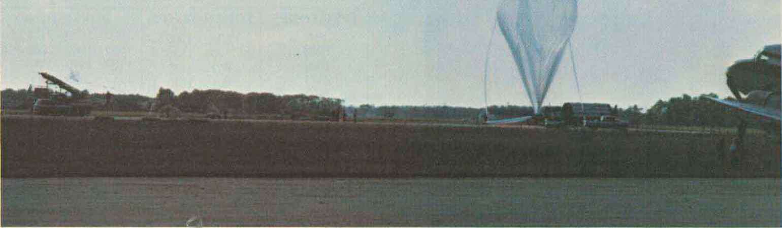
Balloon being inflated. Radio package can be seen hanging from the truck on the extreme left. 12 73 Magazine * June, 1981
Flight Payload Specifications:
| Weight |
250 lbs. |
| Repeater |
Transmitter Power: 1 Watt Frequency: 147.33 MHz Modulation: FM, 3.54-kHz deviation Antenna: Modified ground plane Mode: Simplex/duplex, commandable |
| Link: |
Transmitter Power: 1 Watt Frequency: 144.33 MHz Modulation: FM 3.5-kHz deviation Antenna: Modified ground plane |
| Beacon: |
Transmitter Power: 80 milliwatts Frequency: 432 MHz Mode: CW Antenna: Turnstile |
| Power Supplies: |
+ 16 V dc, 35 Ampere/hour + 15 V dc, 1 Ampere/hour |
| Total Current Drain: | 1 Ampere/hour |
| Command Signals: | + 24 Volt pulse, 80-ms duration |
Much though and head scratching followed, during which time the matter was chatted up on the air with anyone who would listen Ron Nurnberg VE4KA became interested and, after some discussion, it was decided that a ''simplex" repeater would be flown. Although the title 'simplex repeater" seemed incredible to some amateurs who heard last-minute publicity announcements some time later, the concept was fairly straightforward. Two repeaters would be constructed back-to-back. One would accept input on 144.33 MHz from the ground control station and retransmit on 147.33 MHz. The other would accept input from amateur stations on 147.33 MHz and retransmit on 144.33 MHz. This would be our "simplex" mode using a common simplex channel A solid-state relay system would ensure that when either transmitter was operating, the receiver of the opposite pair would be muted Normal duplex repeater operations on 144.33/147.33 or 147.33/ 144.33 were also possible upon command. The 3-MHz spacing was selected to give protection against desensing of the unmuted receiver This was necessary as it would not be possible, due to restricted space, to include a duplexer for a normal 2-meter repeater split.
The word started to get around about the crazy things being planned out at Gimli, Barry Malowanchuk VE4MA came forward with a plan to include a low-power 432-MHz beacon in the package. As an L-band radar reflector was mounted on the balloon, it was suggested by members of the group that "balloon-bounce" communications might be attempted. The ideas were coming forward, but still the problems of components and hardware remained. The slowly growing team of helpers began to chip in equipment and bucks where they could A massive scrounging spree for expensive or hard-to-get items was directed towards local electronics stores and other businesses. Larry and Max reworked two Marconi DT-85 transceivers for use as the repeaters, and Ron VE4KA set to work on the control circuitry.
Because of the anticipated current drain, power was a problem! Numerous suggestions were made ranging from dry cells to gel batteries, but due to the high

- "Skyhook" balloon at about 1000 feet, just after liftoff:
costs, these ideas were discarded in favor of a bank of silver cells which had been formerly used for rocket experiments. Hugh McKay VF4HC was given the somewhat tedious task of charging and discharging the battery pack to a very strict program to ensure that the maximum battery life would be available "come the day."
Because the design operating altitude was to be about 100,000 feet,
the package would have to be insulated against the extremely low
temperatures and sealed against the rari-fied atmosphere as none of the
equipment had been originally designed to operate in a partial vacuum.
One local amateur worked for a company which used explosion-proof
electrical ¡unction boxes. These were made of 3/4" thick aluminum
alloy, with inside 
- Ron VE4KA working on the repeater package.
dimensions approximately 19" X 12" X 12" and weighing an incredible 95 pounds each! Two such boxes were diverted to the project and became the air-tight equipment enclosures we needed,
Thus most of the equipment was acquired and assembly of the flight package began during the first week of July. The radio equipment was installed In a compartmented aluminum box 12" X 17" X 3" with two receivers in one compartment and the transmitters in separate compartments. Connections between the compartments was via feed through capacitors. Control of the package was of paramount concern. No control equipment, either digital or tone, was readily available. However, on each high-altitude experimental balloon, several command functions are required, such as to open a helium valve to cause the balloon to descend or to dump ballast to cause it to ascend. Command functions for onboard experiments also are provided. A Command Instrument Package (CIP) is
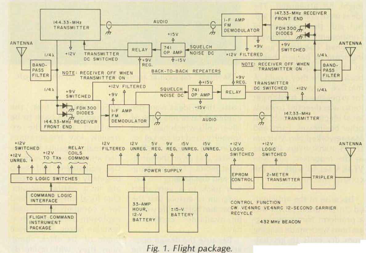
flown for this purpose. A system had to be devised which would convert the CIP output, consisting of a +24-volt pulse of 80-ms duration to a logic level which would actuate the specific functions of our experiment, Ron VE4KA, being responsible for the control circuitry, with assistance from Keith Jonas VE4YA, constructed a system of optical isolators and digital latches which effected the required command sequences. In addition, op amps and digitally-actuated relays were used in the repeater when operating in the duplex mode. Failing to manufacture a suitable bipolar supply to operate from the battery pack, we were forced to rely on Radio Shack D-cells hastily wired together to provide the 15 volts required for these op amps. This proved to be the Achilles heel of the whole operation! Fig, 1 shows a block diagram of the repeaters and command system.
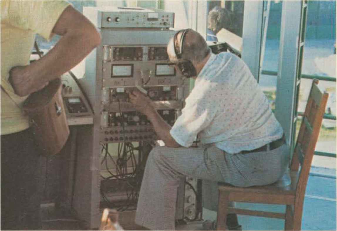
During the later part of the assembly period, Bill Bowman VE4AFO/UB had been busy assisting with assembly of the equipment, helping to prepare the deactivated airport control tower for use as the ground station, building antennas for HF communications, and running errands for the constructors, He also managed to spend some time on the local 2-meter repeaters advertising the Gimli activity, arranging for the loan of equipment, and recruiting help where he could find it,
I was recruited at this time and did some publicity work on 20 meters and on the various 75-meter nets in the adjoining states and provinces. This I found a little frustrating. After accepting the information I had to offer, sometimes a little skeptically, most people would ask for a launch date and time. This I was not able to give! The problem was that this balloon would be a real monster! It would have an inflated volume of 1.5 million cubic feet and the combined length of the balloon, payload, and flight train, consisting of the ladder structure and collapsed parachute, would be 600 feet It was therefore necessary that, at launch time, there be no more than a 5-mph wind velocity difference between ground level and 400 feet, or else the balloon could be damaged. Thus the launch date and time were highly dependent on local weather conditions. Regarding the size of the balloon/package combination, one of the group described it as 'like flying a large condominium to a height of 22 miles."
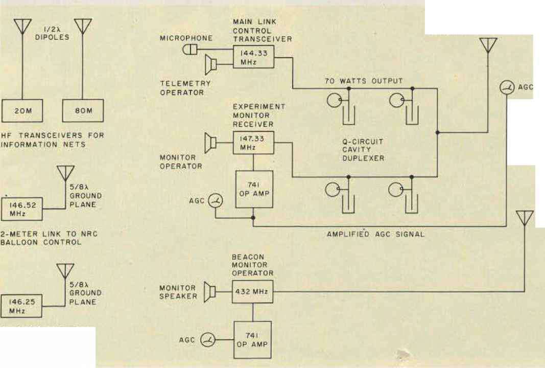
During the later stages of the airborne package construction, the ground station was being prepared. Most of this equipment was obtained on loan from various amateur and business sources, while some specialized equipment was obtained from NRC. Dick McGuire VE4HK ran a courier service between Winnipeg and Gimli! He delivered purchased and scrounged equipment to the construction team. The ground 2-meter transceiver was an Icom 280 driving a KLM 70-Watt linear amplifier. The main tracking antenna, a 4- x 6-element yagi array, was jointly constructed by Vic Grant VE4VG and Joe DeLaronde. It was mounted on an Andrew pedestal for manual control of azimuth and elevation. Also mounted on the pedestal was a remote receiver AGC meter to assist the antenna operator in tracking the balloon Fig 2 is a block diagram of the ground station equipment used.
The Federal Department of Communications had been kept informed of our plans at all times and had approved the call VE4NRC for use during the flight, the
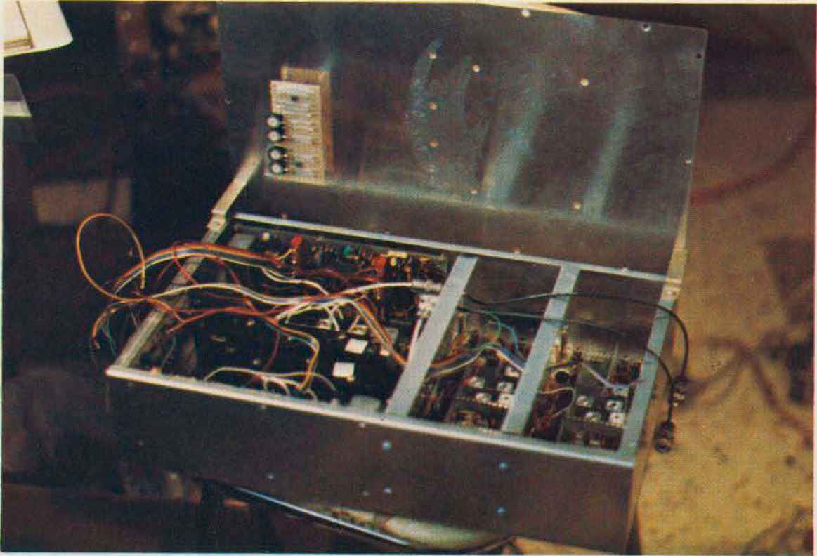
The repeater package with two receivers in the left-hand compartment and the transmitters in two separate compartments on the right sponsor being Kathy Toms VE4YI. Sponsorship was later transferred to VE4KA in order that Advanced class privileges would be available.
At last the day came, after many days of payload checks, weather briefings, false alarms, and final preparation of the ground station. At 0012Z on July 27, 1979, the balloon was launched, not looking like a conventional hot-air balloon, round and graceful, as I for one expected, but more like a sad sausage skin which someone had forgotten to fill! At first, as I
watched from the balcony of the control tower along with dozens of local amateurs who had heard that the launch was imminent, the balloon went straight up, then it drifted off to the southeast over Lake Winnipeg. It appeared to hang motionless over the southern end of the lake for several hours. Later, under the influence of upper winds and the Earth's rotation, it would travel westward across Manitoba and into Saskatchewan.
Amateur operations commenced at 0025Z, thirteen minutes after lift-off when the balloon was at about 15,000 feet, the first contact
4X6-ELEMENT YAGI ANTENNA E5 Db GAIN
ANTENNA CONFIGURATION
2-METER YAGI MOUNTED ON ANDREWS PEDESTAL FOR AZIMUTH AND ELEVATION CONTROL
12-ELEMENT YAGI FIXED
2 METERS FOR LOCAL COMMUNICATIONS AND COORDINATION OF FLIGHT LINE TESTING

- Balloon package prepared for flight
being VE4BE at 0027Z Bill VE4AFO/UB was in his element, feeling like a DX operator in a pileup! Alas, it did not take long for the amateur community to find the ground control input frequency, but this was being monitored and no station attempting contact on the control frequency was acknowledged, We had little to fear! With 2000 Watts ERR from the base station through its antenna system, we could certainly "capture" the flight uplink receiver! Although some interference continued, a great many contacts were made until the experiment was temporarily shut down at 0830Z.
There were a few amusing contacts. While I was putting out the word on 75 meters, I ran into two amateurs in Minnesota and I broke into their QSO to tell them what was taking place. A few minutes later I heard them make contact with the control station, and a short time later, again on 75 meters, I heard the following;
"How high did that guy say the balloon was?"
"102,000 feet, but no one in his right mind would put a repeater on a free balloon. It must be tethered."
Short pause.
''Where the devil would they get a rope 20 miles long?"
Long pause!
My favorite story is the one about the amateur in northern Nebraska who was called by nature in the early hours of the morning Noticing that the scanner on his handie-talkie by his bedside was stuck on one frequency, he took it with him Perhaps to this day he doesn't believe that he spoke to an operator 500 miles away on 147.33 simplex, with a 1-Watt handie-talkie with, a rubber ducky antenna white sitting on his own john!
Many similar tales made our 30 hour day more bearable!
The experiment was turned on again at 1010Z, but insufficient power remained in the ±15-volt power supply to operate the repeater in the simplex mode. The 147.33-MHz transmitter was commanded on continuously and successful operation continued in the 144.33/147.33 duplex mode until termination at 1529Z. During the 15 hour, 17-minute flight, over 500 contacts were made in 5 states and 3 provinces From calculations and a Fresnel plot, the theoretical radio range from 102,000 feet was 451 6 miles, information provided by the NRC weather service indicated that there were no significant inversions during the period of the flight Analysis of the actual contacts made indicates that the actual radio range was indeed very close to the theoretical.
It was also noted that differences in polarization at ground stations, eg: vertical, horizontal, or circular, had no apparent effect on the received signal strength.
Hugh VE4HC and the 432-MHz monitors.
A drop in signal strength of about 30 dB occurred approximately every 74 minutes The regularity of this phenomenon leads us to suspect that balloon rotation resulted in eclipsing of the flight antenna system, Rotation was confirmed by telescopic sightings.
The 432-MHz beacon experiment was not successful as the unit was inadvertently turned off by the balloon command officer and it was only just before termination that, when supposedly switching it off, it was in fact switched on, and we could hear the signal clearly from almost 400 miles away. No reception reports were received.
The flight was terminated near Broadview, Saskatchewan, and a search team quickly located and recovered the amateur package which was safely returned, undamaged, to Gimli the next day.
As a result of this flight and the professional attitude of the amateur fraternity, amateurs in general, and the recently formed Canadian Amateur Radio Research Club (CARRC) in particular, have gained a measure of credibility and recognition from the scientific and industrial commumunity.
At present, members from the Greater Winnipeg area, together with an Ottawa chapter, are working on a flight experiment expected to be included as a passenger on a balloon flight during the summer of 1981. The design of the package calls for:
1. A microprocessor which will act as the control center for other experiments on board. This will demonstrate that programming and execution can be controlled from the ground Commands will be transmitted from the ground to activate various functions of the experiment, e g , to turn equipment on or off, etc Command verification and analog data from the experiment (temperatures, supply voltages, etc.) will be transmitted back to the ground via Pulse Code Modulation (PCM).
The data transmissions will be decommutated at the ground station and the data will be analyzed in real time. Magnetic tape recordings will preserve data for further analysis at a later time.
PCM format: 1.5 kilobits per second, bi-phase level mainframe length—20 words; word length 9 bits (8 data bits + 1 bit); sync word length 18 bits The PCM will be transmitted on an FM subcarrier, frequency modulated on the main telemetry down-link.
2. The radio experiments will consist of:
(a) a 2-meter duplex repeater with input on 144.33 MHz and output on 147.33 MHz.
(b) a 10-meter-to-2-meter transponder. This will consist of a 10-meter SSB input with a 2-meter FM output.
(c) a UHF beacon, tone modulated.
We have been informed that, as we would be passengers on the flight, we must keep the package weight down to 50 pounds and the size down to 1 cubic foot. Ah, well, the impossible just takes a little longer!
It is hoped that we will be able to publicize the next flight rather better than the last Our publicity man will probably send information to local net managers tn Canadian provinces and the northern United States, so perhaps you should monitor your local net frequencies for up-to-date news on the progress of our next venture The results of the proposed experiment may
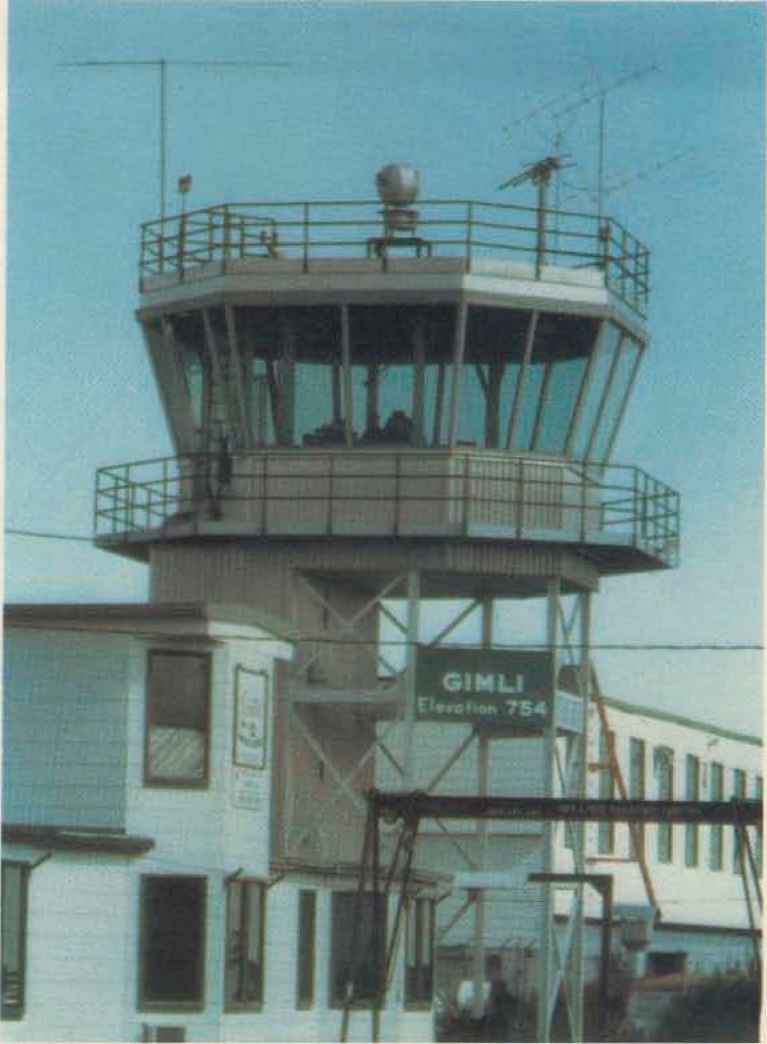
The Gimli control tower. The 4 x 6 element yagi for 2 meters is seen to the right and the 432-MHz beam can be seen to the left published in a future article from CARRC, Box 473, Pinawa, Manitoba, Canada R0E 0H0
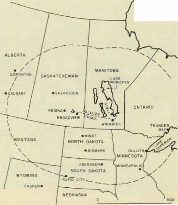
fig, Dotted envelope shows the theoretical maximum coverage throughout the flight.